 rena's websight
 ddr pad build
As a big fan of rhythm games I’ve sunk thousands of hours in beatsaber, osu, djmax, project diva etc, but one thing I’ve never really had is a good way to play Dance Dance Revolution at home. Have you ever used one of these?

They’re irredeemably terrible. They move around and fold up as you play, and the best way to use one of these is to throw it in the trash tape it down to a sheet of wood so it can’t move anywhere. Even then it’s a pretty limiting factor for playing ddr and was generally putting me off playing.
Another option is to buy a cheap chinese metal pad like the one below.

A few years ago I managed to score one of these for cheap second hand, and to be honest it was a major upgrade. It had a few major flaws though.
The first is that the sensors weren’t really reliable. They’re usually constructed out of crap like cardboard that wears out and needs replacing, and mine was already second hand when I got it.
The second issue is that it’s massive, heavy, and hard to store. And the final, related issue is that the hard metal parts, like the brackets around each step (which mine had a lot more of than the above picture), hurt your feet if you try and play barefoot.
In the end I moved and ended up living upstairs with only a wooden floor to play on so I gave up on playing much DDR anyway. But I always wanted to be able to build my own controller to play it optimally.
Recently we started playing again for the exercise and got one of the crappy floppy pads at the top, and very quickly outgrew it.
the design
The design of our pad is based on the DanceForce V3 by Promit. The sensors use a pressure sensitive plastic material called Velostat as variable resistors, which are extremely sensitive and don’t quickly wear out like mechanical designs (e.g. using a thin material between your contacts that compresses) and is a lot cheaper than commercially available sensors. Velostat is a fascinating material which I’m sure has a lot of applications for hacking and making and I’ve never used it before so I’m excited to use it in my build. Additionally Promit’s DanceForce V3 is the most elegant and easy to build diy DDR pad design I’ve ever seen so check it out at the link above, this build is pretty similar so you can use my build log as supplemental material if you need it.
I’ve created a CAD model of the design in fusion 360 which can be downloaded here and exported some renders of the design too. Note that the dimensions and materials are slightly different to the DanceForce V3 design since I metric-ified it and adapted it to what’s available locally for us.

The layers shown on the rightmost render are, from bottom to top:
- A base of 12mm plywood
- A layer of copper tape under each sensor location and all connected together to form a common ground
- A layer of 3mm mdf everywhere there aren't sensors (with a small border around each sensor)
- Velostat sheets on top of every sensor location
- A polycarbonate sheet to top off every sensor with another layer of copper tape on the bottom
- A neoprene layer on top of each sensor to make it feel good
- A sheet of polycarbonate across the whole top to enclose it
The bill of parts with their prices is as follows. I’ll try to include where I got some of the parts from, but some of the links may have expired.
| Material | Unit cost | Quantity | Cost | Notes |
| 1mm polycarbonate (includes cutting) | £27 | 1 | £27 | makes 1 with scrap |
| 12mm plywood | £25 | 1 | £25 | makes 2 with scrap |
| 3mm mdf | £15 | 1 | £15 | you only need a little bit |
| 0.1mm Velostat | £18.48 | 1 | £20 | should last you a few pads |
| Copper tape | £8.68 | 2 | £17.36 | seems unnecessarily expensive but does the job really well |
| Teensy 4.0 | £18.49 | 1 | £18.49 | there are cheaper alternatives but the teensy is really good |
| Neoprene | £12.00 | 1 | £12.00 |
Total cost of materials is £133.33, but amortized over multiple pads it probably comes out to just over £100. There might be something I missed but that seems pretty good to me.
The cuts that need to be made are:
| Material | Quantity | Dimensions (mm) |
| 12mm plywood | 1 | 850*825 |
| 3mm mdf | 2 | 255*255 |
| 3mm mdf | 1 | 235*235 |
| 3mm mdf | 2 | 255*137.5 |
| 3mm mdf | 4 | 117.5*25 |
| 3mm mdf | 4 | 50*12.5 |
| 1mm polycarbonate | 1 | 825*825 |
| 1mm polycarbonate | 4 | 250*250 |
| 1mm polycarbonate | 2 | 190*100 |
I recommend getting a table saw if you don’t have one to cut the wood, but we got the polycarbonate cut by the people we bought it from. I tried cutting some polycarbonate on the table saw and it was kinda sketch, although I’m sure you can do it if you know what you’re doing, and I’ve heard it’s easier to cut by scoring it with a good craft knife instead if you really need to.
the build
step 1 - cut the wood
It’s build time, the first step is to cut the 12mm plywood base to 850x825. This divides into nine 275x275 panels, and an extra 25mm at the top for wiring and such.

Note that I drew out the top 25mm section, and then divided the remaining space into a 3x3 grid. I drew in arrows in the up, down, left, and right spaces to show us where they were going to go, and that’s where I stuck the copper tape in step 2.
I then cut the 3mm mdf parts listed above and arranged them on the base, but I didn’t glue them yet.

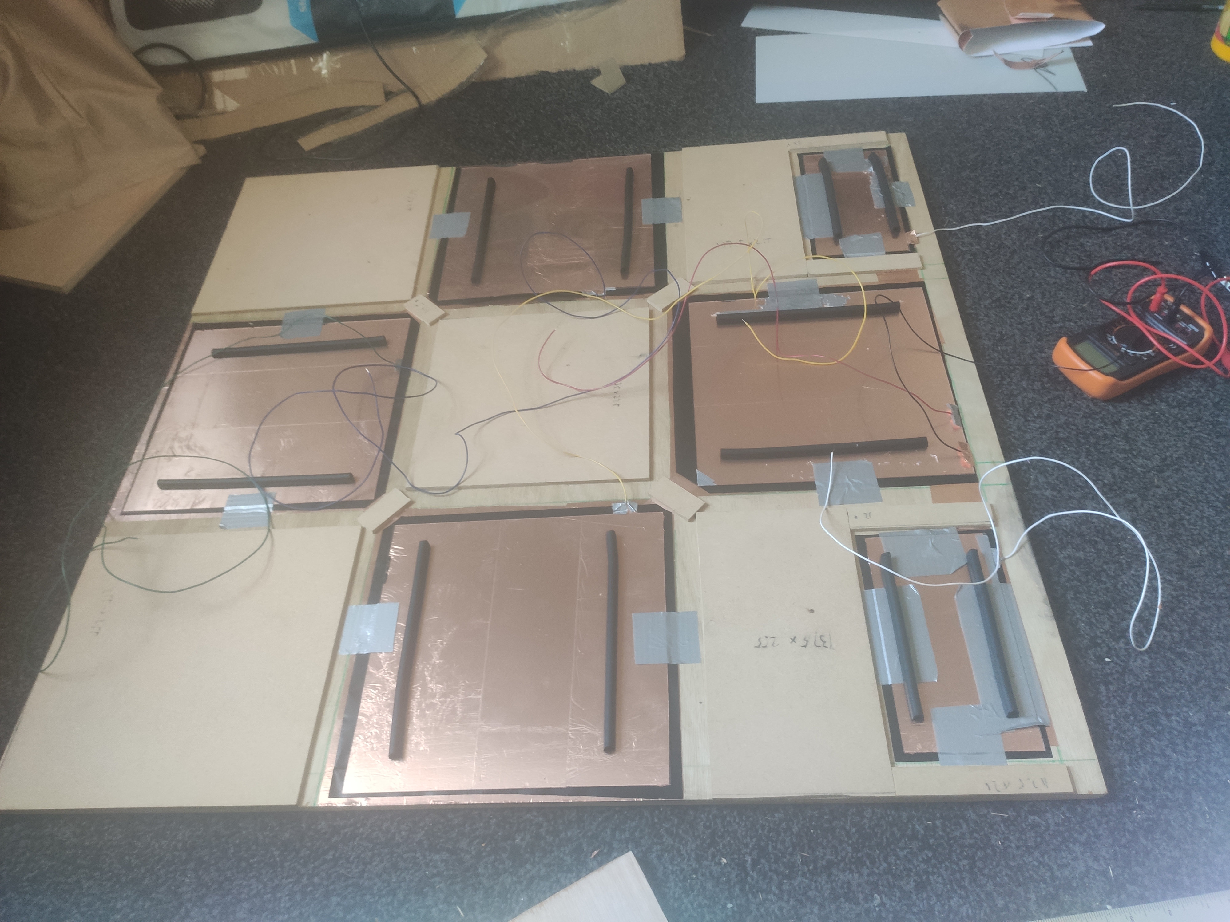
step 2 - stick down the copper common
The next step is to stick down the copper tape under each sensor location (the arrows I drew), including a start and select button. Join them all together with additional strips of tape, by connecting the arrows at the corners, and the start and select button across from the up panel.

I found the best way to stick the tape down flat and straight was to peel back about an inch of the tape and stick it roughly in the top left corner of where you want to tape. Then check that it lines up to the bottom by pulling the opposite end of the tape taut. If it doesn’t you can restick the top until you get it right. Once it’s right, use a small mdf strip to flatten out the top from left to right, and then run it all the way down along the tape as you peel off the back. I had to apply some force but my tape came out really cleanly after I learned this. If you look at my right panel above, you can see the point at which I gave up doing it with my hands, after that particularly messy panel.
It’s worth using a multimeter on continuity mode as you go to check all the tape conducts. I found that about half an inch to an inch of overlap made the connection really solid between strips, but this copper tape is a lot higher quality than some copper tapes I’ve used in the past (and they claim the adhesive is even conductive).
Finally, I soldered a wire to a small strip of copper tape and stuck that to the copper common at the top, so I could hook it up to the ground of our teensy board. The way I found to do this is to just take a bit off the backing off the end of the tape and fold it over on itself so there’s no sticky bit, leaving just a copper tab to solder to.
step 3 - sensor construction
To construct the sensors we lay velostat on one of the sensor locations (in this case, the up arrow). We then stuck copper tape on one side of a 250x250 piece of polycarbonate, plus soldered a wire to a small strip of tape like with the common, and stuck it on so it was sticking out a bit. Then we sandwiched the velostat between it and the copper common and tested it by setting my multimeter to continuity mode and connecting the probes to the two wires.
Note that in this video we used scrap pieces of polycarbonate and velostat since we didn’t have the final parts cut yet, but in the end we actually added masking tape around the outside of the polycarbonate to prevent any shorts or sharp edges poking into the velostat, at which point we realised you should probably cut the velostat to about the same size as the polycarbonate so it doesn’t stick out much.
Then we simply taped the whole thing down with duct tape at the edges so it can’t move. Try not to use too much tape or it puts pressure on the sensor and reduces its effective range. You should test each one with a multimeter to make sure it still works well, we found we got a range of about 1000 ohms without any pressure down to 0 when fully pressed.
After this, the neoprene was cut into 250x250 squares and added on top of each sensor, and then the 825x825 polycarbonate top layer was added to the top and secured down at the corners.

Note that we originally used rubber draught insulator strips as pictured here but we didn’t like how they felt. On top of this we had to do a bunch of other trial and error to make the sensor work well and feel nice, so it’s a good time to go over the lessons we learnt in the process.
1. voltage dividers are needed to read the sensor accurately
We originally connected our velostat sensors directly to the analog pins of our teensy so that the circuit looked like this:

And it kind of worked but we found that even though we could read a smooth 1k ohms down to 0 ohms when the sensor was pressed using a multimeter, that when we had the sensors in place and hooked up to the teensy, it really barely worked at all. With a lot of software tweaking and setting manual activation levels for each sensor, we managed to get digital outputs from it, but it really didn’t feel good and we were only getting a range of like 20-30 values out of the analog to digital converter on the board. (For reference, the teensy gives you a 0-1023 value from the analog pins, 0 for 0v and 1023 for 3.3v).
At first I thought it was the sensor construction. Originally the sensors worked fine when measured by multimeter, but I figured that sticking them down screwed something up and reduced the sensitivity we were getting. It’s been a while since I’ve touched anything electronics so at the time it wasn’t really obvious to me how we could make the range on the analog pin any better.
After a good few hours of trial and error we realised that the velostat basically works as an unknown resistance value, and that’s ideally what we want to detect rather than some arbitrary voltage level that passes through it. I googled and found out that the standard way to do this is using a voltage divider. The circuit for that looks like this:

The way a voltage divider works is that it produces an output voltage that’s less than the input voltage, and that you can tweak by changing the two resistor values. The values are related by this equation:
If you choose a value for one of the resistors, you can then rearrange the equation to solve for the other one. For example, if your sensor is connected to ground and your known resistor is connected to Vcc, you can solve for R2:
On the other hand, you could also make your common layer VCC and connect your sensor to gronud instead, in which case you’d need to solve for R1:
We decided that making the copper on our base be the ground plane was probably more sensible, so to implement this all we need to do on the hardware side is connect a resistor from each analog pin to Vcc. We chose a 1k ohm resistor since I figured we’d get more accuracy if the value was close to the value we were trying to measure. I did this hackily to test if it worked by just cutting each wire to expose a contact and solding a resistor there, which made our wiring a nightmare, but eventually I have to go back and tidy it up anyway so that the wiring and teensy are integrated into the build.

This also acts as a pullup resistor so you don’t need one of those anymore, the pin mode can just be set to INPUT. The sketch for reading this and calculating the resistance is something like this:
// Solve R1 in voltage divider equation (if your sensor is connected to VCC)
// R1 = R2 * Vin / Vout - R2
float getResToVcc(int pin) {
  float vout = analogRead(pin) / INPUT_MAX * VIN;
  const float R2 = KNOWN_RESISTANCE;
  return R2 * VIN / vout - R2;
}

// Solve R2 in voltage divider equation (if your sensor is connected to ground)
// R2 = (Vout * R1) / (Vin - Vout)
float getResToGround(int pin) {
  float vout = analogRead(pin) / INPUT_MAX * VIN;
  const float R1 = KNOWN_RESISTANCE;
  return (vout * R1) / (VIN - vout);
}

void setup() {
  Serial.begin(115200);
  pinMode(A0, INPUT);
}

void loop() {
  while (true) {
    float resistance = getResToGround(A0);
    Serial.println(resistance);
    delay(50);
  }
}
And now when we test the pad we also get perfect analog inputs we can expose too :D
The resistance starts out at about 1000 ohms and drops to about 500 with a kilogram or two of pressure. It completely maxes out if you stand on it at all, which is fine.
I’ve seen a lot of ddr players online complaining that velostat doesn’t work well in pad builds, and I’d guess it’s probably because they aren’t using it correctly. Honestly, it’s not worth using without the voltage divider imo. That’s probably the biggest lession we learnt which is why this section is so long, the next few points are fairly minor in comparison.
2. try not to have too much excess velostat
We found that having too much excess velostat around the sensor made it harder to fix them down with tape, and that having too much tape pressing down on the velostat at the edges reduced the reliability of the sensors. It’s pretty easy to fix, if you make sure the copper doesn’t go up to the edges of the polycarbonate, or just mask it off like we did, it doesn’t need to be any bigger anyway and then you’re just sticking polycarbonate down to the base without the tape touching any velostat.
3. neoprene is the best material to go above each sensor
We experimented with a few ways of making the sensors feel good by putting different materials between our sensors and our top polycarbonate. It’s worth noting that the sensors actually work without anything between the polycarbonate on the top of the pad and the top layer of each sensor, it just takes a bit of pressure to actually press them, which isn’t ideal for the arrows at least.
The first material we tried were rubber insulation strips (called draught insulators in the UK) as on the DanceForce V3. We found that the polycarbonate was too floppy and buckled in the middle between the two strips though, and I didn’t like the feeling of it. Maybe if the top layer was more solid it’d work fine, and honestly thicker polycarbonate might work better anyway.
I ended up pulling out the rubber strips and just using 250x250 squares of cardboard instead. The cardboard we picked was slightly too thick for the pad which put a bit of pressure on the sensor, but we found it worked really well when we adjusted for that. The cardboard noticably buckled when you stood on it though, and I figure it would have worn out before long. In search of replacement materials I went online and ordered some 1.5mm sheets of rubber and neoprene.
We tried the rubber first since I figured it’d be the best option. The neoprene just seemed too light and soft to me, and even though they were both meant to be 1.5mm, it felt thinner. The rubber performed pretty well, but it was a lot stiffer and more solid than I imagined, and didn’t feel that rubbery when it was placed under the polycarbonate. Additionally it was quite heavy, and put a decent amount of pressure on the sensors, which made it harder to determine a baseline level of pressure for each one. Ultimately, we found that the rubber would stick to the polycarbonate both on the top of the sensor and the top layer of the pad, which stopped the value from returning back to default as fast when you released it. While we probably could have solved that somehow, the rubber kind of sucked overall so we decided to try the neoprene instead.
I then cut the neoprene and replaced the rubber with it, and damn it feels amazing. The pad is now super sensitive to any presses, and the value returns to default quickly after releasing, so the presses don’t last any longer than you mean them to. Additionally the neoprene just makes the feel a lot better.
Annoyingly both the neoprene and the rubber comes in 1000x500 sheets, which is exactly enough for 8 arrows (for two pads), but doesn’t leave any spare for start and select. To be honest though we found that the sensors work even without anything there and just require you to press harder, so no big deal this time, and the neoprene is cheap anyway (£12 for 1000x500) so it wouldn’t be that big of a deal to buy a bit extra anyway.
The pad is super sensitive now and works really well, at least at our level, so in the next section I’ll share the final sketch we used for our teensy to show how we actually use the sensor values in the end.
step 4 - programming the teensy
The final step is to program the teensy. To be honest, we started doing this even before we had all the parts, and iterated on it repeatedly while we were trying to get the most out of our sensors in the section above.
In the end, when read using our voltage divider and the getResToGround function above, we found that our sensors all have about 1000 ohms of resistance when unpressed, but that one had a slightly lower value which occasionally dipped below 900. What we decided to do with this value in the end was to clamp it to the range 0.0 - 850.0 to discard any extra values above that, and then normalise it to the range 0.0 - 1.0 and invert it so that it was 0 by default. As long as the sensors are above 850 when unpressed then, (including just standing on the “dead” parts of the pad, which to be honest wasn’t really a problem with our final construction), the value we end up with is an analog value of 0, and it increases towards 1 as you put pressure on it.
Our final sketch exposes both an analog value from each sensor, plus a digital value according to a threshold, and looks like this:
// DDR pad sketch, the wiring basically has a ground plane under each sensor, then a velostat layer,
// then a polycarbonate layer with copper on the bottom that goes to the pins listed below.
// Additionally those pins are tied to VCC with a 1k resistor to act as a voltage divider (the
// resistance of that resistor is KNOWN_RESISTANCE and is used to solve for the resistance of the
// velostat.

// The pins used for each sensor
#define PIN_COUNT 6
const int PIN_LEFT = 14;
const int PIN_DOWN = 15;
const int PIN_SELECT = 16;
const int PIN_RIGHT = 17;
const int PIN_UP = 22;
const int PIN_START = 19;

// The normalized threshold at which to activate each gamepad button
const float FIXED_THRESHOLD = 0.35f;

// Some arrays to make it easy to poll all the sensors and report gamepad inputs back
const char* pinName[PIN_COUNT] =    { "UP",   "DOWN",   "LEFT",   "RIGHT",   "START",   "SELECT"   };
const int pins[PIN_COUNT] =         { PIN_UP, PIN_DOWN, PIN_LEFT, PIN_RIGHT, PIN_START, PIN_SELECT };

// The logic level voltage
const float VIN = 3.3f;

// The max input from the ADC for the analog pins (the teensy has 0-1023)
const float INPUT_MAX = 1023.0f;

// The known resistance value for the other half of the voltage divider
const float KNOWN_RESISTANCE = 1000.0f;

// The "max" value after which we clamp off the resistance of each sensor. We found that the base
// level was generally 1k ohms without any pressure on it, but that one sensor was just under 900
// due to differences in construction. Capping it off at 850 basically means that >= 850 is 0 on
// the analog input and as it drops down to 0 then the analog input goes towards 1.
const float R_MAX = 850;

// Solve R1 in voltage divider equation (if your sensor is connected to VCC)
// R1 = R2 * Vin / Vout - R2
float getResToVcc(int pin) {
  float vout = analogRead(pin) / INPUT_MAX * VIN;
  const float R2 = KNOWN_RESISTANCE;
  return R2 * VIN / vout - R2;
}

// Solve R2 in voltage divider equation (if your sensor is connected to ground)
// R2 = (Vout * R1) / (Vin - Vout)
float getResToGround(int pin) {
  float vout = analogRead(pin) / INPUT_MAX * VIN;
  const float R1 = KNOWN_RESISTANCE;
  return (vout * R1) / (VIN - vout);
}

// Set an axis value from an index, the teensy doesn't have this for some reason
void setAxis(int axis, float normalised) {
  int value = (int)(normalised * 1024.0f);

  if (axis == 0)
    Joystick.X(value);
  else if (axis == 1)
    Joystick.Y(value);
  else if (axis == 2)
    Joystick.Z(value);
  else if (axis == 3)
    Joystick.Zrotate(value);
  else if (axis == 4)
    Joystick.sliderLeft(value);
  else if (axis == 5)
    Joystick.sliderRight(value);
}

// Set up our serial settings and input pins
void setup() {
  Serial.begin(115200);

  // The pins don't need a pullup or pulldown because they're tied to VCC by the 1k resistor which
  // acts as a pullup
  for (int i = 0; i < PIN_COUNT; ++i)
    pinMode(pins[i], INPUT);

  Serial.println("beginning");
}

// Our main loop
void loop() {
  // Go through the list of sensors and poll them, sending gamepad inputs over usb
  for (int i = 0; i < PIN_COUNT; ++i) {
    // Get the resistance of the sensor. Use getResToVcc instead if your common is VCC and your
    // resistors connect each sensor to ground instead
    float sensorResistance = getResToGround(pins[i]);

    // Invert and normalise the sensor values, resulting in a 0 to 1 value that goes to 1 when the
    // sensor is pressed
    float sensorValueNormalised = 1.0f - constrain(sensorResistance / R_MAX, 0.0f, 1.0f);

    // A little debug logging for the serial port
    Serial.print("sensor ");
    Serial.print(pinName[i]);
    Serial.print(": ");
    Serial.print(sensorValueNormalised);
    Serial.print(" (raw ");
    Serial.print(sensorResistance);
    Serial.println(")");

    // Report gamepad inputs
    Joystick.button(i+1, sensorValueNormalised >= FIXED_THRESHOLD);
    setAxis(i, sensorValueNormalised);
  }

  Serial.println("");
  delay(5);
}
So there you go. A bit involved in the end, but the final result is much better than I could buy for the cost, and probably better than I could buy for many times the cost around here. The final cost of all the materials was £133.33 and left extras for another pad, and amortized over two pads comes out to about £104 each, which still leaves a lot of spare 3mm MD.F That doesn’t count all the tools we ended up buying or any extra stuff we bought to experiment with, but I’m sure I’ll find more stuff to do with all of that.
And now, there are a few todos that I may or may not go away and do and then come back and update this.
future todos (to be updated, maybe)
tidy up the wiring
The wires currently just hang out of the pad near the up arrow, which isn’t ideal. I think maybe I’m going to use a dremel into one of the 3mm mdf sections and make a nice channel for the teensy to go, plus some sort of circuit board with the resistors and such on, and then route the cables to there instead. This probably means we can remove the extra 25mm off the top of the base too. For now I’m just happy it all works though, and that we can play DDR every day on it.
seal off the edges
The way the pad is constructed currently leaves the edges of each sensor open, since the 3mm mdf raises the polycarbonate off the base to leave gaps for sensors. We’ll probably do this either by adding some wood or some other material all the way around the edges, or maybe just sticking 3mm mdf strips in each of those gaps (which might involve moving the sensors a little bit).
Update 2021-07-26: I’ve now done this by cutting 1cm wide mdf strips that just fit in the edges and makes the wall of the pad all the way around just solid wood. I’ve skipped the top sensors for now since I’ve not yet redone the wiring, but the rest are sealed off like this now and it feels fine. Interestingly it actually stops the polycarbonate from dropping on the sensors as much which in some cases might make them work better, but I’ve found ours to be robust enough that it doesn’t really matter. There’s still a gap around the edges of the sensors which makes them easy to push down, and the neoprene transfers the force to the sensor really well anyway.


While I was doing this, since I needed to move the sensors a bit anyway to compensate for the wood I added, I also used spray-on adhesive to stick the neoprene down to the sensor, just a little circle in the middle in case we need to remove them again. I then (possible unnecessarily) flattened the neoprene out with a book to make sure it wasn’t uneven.
The result is a very nice finish that makes the pad just look like a 15mm (12mm plywood base + 3mm mdf) sheet of wood with polycarbonate on top, unless you haven’t installed the graphics yet like us, in which case you can just peek straight into it ;)
Add rubber to the bottom
The pad isn’t really susceptible to sliding around, but does rock from side to side due to a slight bend (which we assume is a combination of the natural properties of our plywood base plus the fact the polycarbonate is screwed into the top pretty tightly). This isn’t really a problem while playing and I only noticed while watching Maisy playing, but I think for the sake of our carpet it might be nice to add some sort of rubber sheeting to the bottom anyway.
add graphics
The final final step is to add the graphics to the pad. This involves printing a big ass poster image and gluing it under your polycarbonate base. I have no idea how to do this yet so I’ll have to come back to this step later, but see Promit’s DanceForce V3 for more information.


